Engine test run

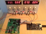
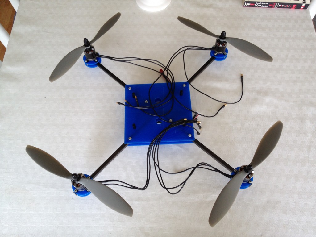
Finally I’ve got some time to continue my work on the copter. I’ve assembled the power distribution cords and hooked it up to an external power supply. Unfortunately my power supply can only give two amps, so there’s some voltage drop outs, but it doesn’t matter for this test. Actually, it means that the voltage regulators on the controller board works great as well.

In this little video you can hear how the engines are changing their speed as the copter is tilted. Sorry for the horrible noise.

[youtube=http://www.youtube.com/watch?v=lcaZebTyx6k&rel=0]

Ping

Just a quick note. I just got the WiFly module working properly 😀 It now auto joins my local WPA2 network, gets a dhcp-address and starts listening on incoming connections. Having a rs232-terminal connected to the Copter main board and an open telnet connection to the WiFly, I can now send another “Hello World” between the two terminals.

It’s getting there…


Sensor raw data

Sensor raw dataToday I managed to get some senors working. I spent quite some time in order to get the TWI/I²C interface working properly, using interrupts etc for interfacing the magnetometer. Still reading some inconsistent values from it though, so I’ll have to look into that a bit further.

The SPI interface to the gyro and accelerometer is currently using old school bit banging, but should now be easily converted into native support. The value readings from the accelerometer are really good. It’s currently set to the ±2g scale, giving me a precision of 0.25mg/LSB. In the live scenario it could be better to use the ±4g scale instead with a 0.5mg/LSB precision.

Hello World!

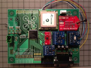
Power onFinally I’ve got one of my most complicated “Hello World!”-applications working 🙂

After soldering the main components, it was time to do some coding. My old AVR programmer didn’t work with todays MCU’s, nor do my laptop have a parallell port, so I had to invest in a new programmer. The AVR Dragon seemed to be a good choice for a hobbyist like me. Switching to the (not so new anylonger) AVR Studio 5.1 seems to be a good way forward as well, though my old environment, with emacs and nice build scripts I had long ago, actually was a lot more streamlined. Being a .Net-developer nowadays, I think the Visual Studio-based AVR Studio will suite me better when everything is trimmed and running smoothely.
Continue reading

Soldering the PCB

Mounted PCBI’ve now done one of the most fun part of the project – soldering the components onto the PCB. While waiting for the PCB to be manufactured, I watched some Youtube videos about soldering flux, like this one. Using desoldering braid works quite well most of the times, but I haven’t used soldering flux before, so I decided to try it out. I worked really nice!

Stupid me didn’t see that there where two dots on the MCU, so of course I managed to mount it in the wrong direction. Doh! So I just had to bring a knife and cut it off, clean the solder pads and buy a new MCU.

Appart from that, everything else worked out fine – nothing burned when I turned the power on 🙂 The power consumption of the board is about 20mA when running at 2MHz and it raises to about 50mA when running at 32MHz.

PCB received

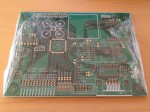
PCB from Olimex I’ve now got the printed PCB and it looks great! I’ve ordered it from Olimex since they could do single boards at a relatively low price. This double-sided board, a bit smaller than the standard 160x100mm, was just €30+shipping. They also have some nice ULP-scripts for Eagle users, so I could do fix the drill sizes etc before sending the files.

Waiting for the PCB

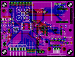
Quadro Copter main board PCBI’ve spent some time drawing the schema of the main controller board and last week I finally got the layout done as well. It was ages since I used Eagle last time, so it feels like I spent more time relearning the CAD software than actually creating it. I’m now waiting for the PCB to be manufactured. This was actually the first time I send a board for manufacturing. Previously I’ve done them myself in the kitchen. But this time I’m not gonna spend time on manually soldering vias etc, so now I’m restless waiting for it to arrive. I hope I haven’t made any errors 😉

Communication

When I first got this crazy idea of building my own copter from scratch, I decided that this shouldn’t be yet another radio controlled quadrocopter, using just a stabilizing system. If it’ll ever gonna take off, it should be more of a real autonomous UAV.

Well, some kind of communication (and most certanly some human input) will be required. Using a regular WiFi network would feel really nice – and would be a good knowledge for future projects as well, regardless.

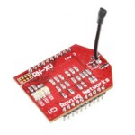
RN-XV WiFly ModuleAfter a couple of minutes at google, I found this little masterpiece: the RN-XV WiFly Module at Sparkfun! The support for ad-hoc networks, WPA-2 encryption and the regular TTL uart serial interface in particular caught my interest.

This means I can have a 115.2 kbps (theoretically a lot more, actually) open connection between the copter and a laptop, or similar, to offload heavy calculations. In flight control, like the stabilizing system, must of course be done by the on-board computer.

I haven’t spent any time testing it yet. I hope it’ll work and there will probably be a separate post on that subject later on.

Sensors

I’ve been thinking some time about the control and guidance system and came up with a rather simple and versatile solution. I’ve been playing around a little with some sensors mounted on breakout boards to make life a little easier. I decided to reuse those in the copter, since I plan to build only one.

Gyroscope

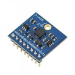
I’ve chosen the L3G4200D 3-axis gyro module from ST. Parallax have it mounted on a breakout board making it easy to interface. Its wide range (250-2000°/s) and fast communication (up to 10MHz SPI) makes it suitable for this project.

Accelerometer

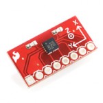
Finding a suitable accelerometer was a bit harder. This’ll probably also be the most important sensor as well. I finally found the Bosch BMA180 triple axis accelerometer mounted on a breakout board from Sparkfun. It also has a wide range (±1g to ±16g) and a fast SPI interface.

Magnetometer

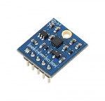
To achieve full 9 Degrees of Freedom (9DOF) I’ve chosen the HMC5883L 3-Axis Compass Module from Honeywell. Parallax have it mounted on a breakout board as well. It has only an I2C interface, but I don’t expect polling it as often as the gyro and accelerometer.

Altimeter

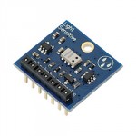
For low level flight (less than 3 meter) I plan to rely on ultrasonic sensors, but for higher altitudes I’ll have to rely on an altimeter and/or GPS coordinates. I haven’t looked into this very much yet, but I decided to go for the MS5607-02BA01 Micro Altimeter Module from Measurement Specialties – just because Parallax had a breakout board for that one as well. It states it has a 20 cm resolution. I’m not sure if I’m believing it…

Electronic Speed Controllers

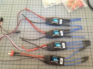
The four speed controllersI decided to go for a recommended set of speed controllers for my engines. The Hobbywing 18A seems to be quite easy to work with and should suit my Tiger motors quite well with their 17 amp maximum continuous current. To my surprise, the engines were ready fitted with 3.5 mm gold connectors, so last night I mounted the ESC’s with  3.5 mm female connectors and Deans connectors for the power supply.

I realized I forgot to measure the overall height of the ESC’s. It turned out that there was a rather thick capacitor mounted at the end of the ESC, making the total height almost 10.5 mm – that certainly won’t fit in the 8 mm gap of the frame. I solved that by adding small splines of acrylic glass on top of the carbon fiber rods, making the gap 11 mm instead. Well, that was the first setback so far on this project. 😉

Building the frame

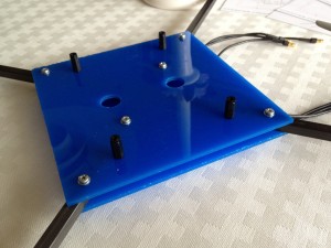
The frameI spent a few hours during the weekend building the copter frame. I first thought of bying a ready made frame, but that’ll wouldn’t be as fun as creating my own. I started with a 8×8 mm carbon fiber rod and mounted it around two 150x150x3 mm acrylic glass sheets. The carbon fiber rods were quite easy to work with. Cutting them with a disc using a Dremel were far easier than I expected. Drilling the holes using a regular 3mm HSS drill worked fine as well, though the drill itself was quite worn out afterwards.

The two larger holes are for the signal cables to the ESC’s and there are two identical holes on the bottom sheet for the power supply cables.

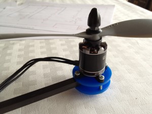
Mounted engineI also made some small discs from acrylic glass to use as supports for the engines. From a small brass tube I got some shims to give the engine mounts extra support (not in the picture). I’m actually quite happy with the result. The whole construction became really torsionally rigid.

Total weight, so far, is a bit below 1.2 kg, including calculated weight of all known components. The PCB with some cables still needs to be added though, but I’m quite confidente that the 2 kg limit won’t be a problem. The result now looks like this:

The frame with mounted engines


Quadrocopter engines

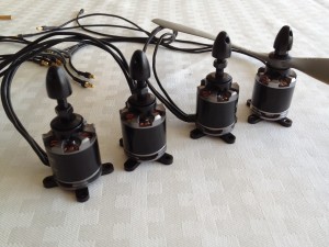
The four brushless engines

The Tiger Motors MT2216 800 kv Coptermotors

Last week I received the four brushless engines for my quadrocopter project from rcflight.se. The MT2216 from Tiger Motors seemed to be quite good for this project with its high performance and still reasonable price. I plan to run them on a three cell LiPo battery with ten inch propellers. That’ll give them 960g of thrust each, almost 4kg of lift in total. So I set a goal of max 2kg total weight of the copter. I think that’ll make it quite maneuverable.

Btw, why do the engine manufacturer specify thrust in g instead of Nm?

The Quadrocopter project

A couple of weeks ago I started building a little quadrocopter. My main reason isn’t actually having it flying nicely, but to learn a bit more in detail about how modern sensors work. All my electronic stuff has been stored in boxes for almost ten years, so I thought it was well about time refresh my mind a bit.

I quite soon realized a lot has happened during these ten years and, among things, found out that my old AVR programmer didn’t work any longer in a modern OS. Nor doesn’t every computer have serial and parallell ports…

Instead of investing in a lot of new equipment, I found an old laptop that actually had a rs232 port. Installing a 32bit version of Windows also solved a lot of driver problems. So, after some struggle, I had a simple development environment up and running and created the mandatory Hello World program on a simple ATmega8515 CPU.

So, now I just needed a fun project to work on. I recently saw this amazing Ted talk about flying robots, and I though I may give it a try myself. Maybe I’ll make it half way and actually make it flying 😉