My today’s Sitecore discovery was that the Sitecore Content Editor have code that is dependent on what’s sent in the Referer header. (Yes, it’s incorrectly spelled in the HTTP standard.)
TL;DR: Set “Referrer-Policy” to “same-origin”. Most other sensible configurations will break Sitecore.
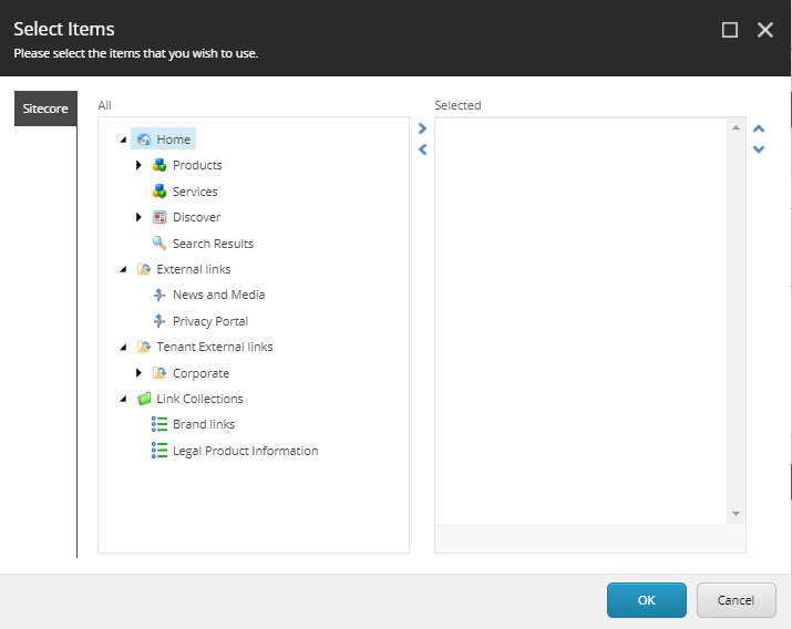
I’ve been working on a project where I found that the content search functionality didn’t work properly in the Content Editor. I found that search results were not limited to the scope of the context item, i.e. results from the entire database was always returned. I also found that no matter how I configured my custom facets, only the global facet where used.
I was just about to file a support ticket for this, and decided to reproduce this in a clean solution and found that it worked just as expected. So obviously we had done something in our solution that broke it. So I started to remove all our own config files, starting with content search related files, but I couldn’t get it working unless I did a full reset of my local development environment. So something fishy was going on here.
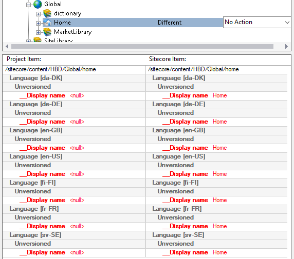
So I hocked up the symbol server in dotPeek and started debugging. Soon I found that the FacetSearcher.GetFacets() always returned just the global facet regardless if I had local facets. This was due to the startLocationItem variable always being the Sitecore root item. Strange…
Digging deeper, I eventually found that the SearchHttpTaskAsyncHandler have a LocationFilter property that reads an id parameter from the query string of the referrer header. If the id parameter wasn’t present, it would just use the Sitecore root item id.
So now I knew the probable cause of this. And yes, we’ve tried to follow most web security best practices in this project, so we had opted for setting the Referrer-Policy http header to strict-origin. This basically means that just the domain name would be sent in the Referer header. Not path nor query string.
So the takeaway from this is to set the Referrer-Policy header to same-origin on the CM role. Never set it to anything that disallows sending the query string to the origin site, i.e. don’t use no-referrer, origin or strict-origin.
But if I removed all we’ve followed most security best practices, such as using proper CSP headers etc. So in this solution we had the Referrer-Policy header set to strict-origin. I.e. the visiting browser would basically just send the domain name and not the path or query string.
Looking a bit deeper in the Sitecore assemblies, it turns out there’s quite many usages of request.UrlReferrer.